
What Is PCB Flex and What Types Are Available?
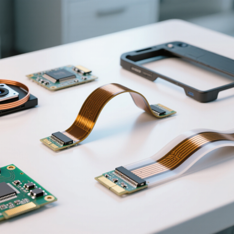
A flexible printed circuit board, often called pcb flex, carries electrical signals through a thin, bendable structure. Unlike rigid boards, it can fold around corners, fit narrow housings, and reduce wiring bundles. Designers commonly use polyimide films, copper conductors, and protective coverlay to create this compact assembly. The result may resemble a slim ribbon running beneath a camera module or along a medical instrument.
PCB flex is not one universal product. Single-sided flex uses copper on one conductive layer, while double-sided flex supports circuits on both sides. Multilayer flex adds stacked layers for denser routing, although its manufacturing process requires tighter alignment and controlled bending. Rigid-flex combines flexible sections with rigid board areas. It can connect a display, sensor, and controller without separate cable assemblies. Dynamic flex supports repeated movement, such as a hinge or robotic joint. Static flex bends during installation and then remains in position.
Material choice matters. Copper thickness, bend radius, adhesive type, and coverlay design influence reliability. A design that works in a handheld device may fail inside a moving hinge. Small details matter. Sharp folds can damage copper traces. Excessive heat can weaken adhesives. Experienced engineers review stack-up drawings, bend zones, testing requirements, and supplier capabilities before production. Still, no design is perfect. Early prototypes may reveal cracking, signal loss, or assembly difficulty. Those findings should refine the design, not be ignored. Understanding each pcb flex type helps teams balance space, motion, cost, and service life with greater confidence.
What Is PCB Flex and How Does It Differ from Rigid PCBs?
PCB flex is a circuit board built on a thin, bendable substrate, usually a flexible polymer film. Unlike rigid PCBs, it can fold, twist, and fit around compact mechanical structures. This flexibility helps engineers connect moving parts, reduce cable assemblies, and save valuable space inside small devices.
Rigid PCBs depend on solid boards that maintain a fixed shape during use. They offer strong support for mounted components and are often easier to inspect. PCB flex behaves differently under stress. Its copper traces must follow controlled bend radii, especially near connectors and stiffened areas. A sharp fold can damage the conductor, even when the surface looks normal. This is easy to underestimate during early design reviews.
Common formats include single-sided, double-sided, and multilayer flexible circuits. Rigid-flex boards combine flexible sections with rigid zones for components and connectors. In practical assembly, flex circuits can reduce wiring errors and improve airflow. However, they may require tighter material control and more careful handling. They are not automatically better. Designers must evaluate movement, heat, vibration, layer count, and repair access. A useful detail is the bend direction. Repeated bending across the wrong axis can shorten service life. Test fixtures should reproduce real movement, not just static inspection. Even experienced teams sometimes treat flex like a thin rigid board, and that assumption can create avoidable failures.
What Is PCB Flex and What Types Are Available? - What Is PCB Flex and How Does It Differ from Rigid PCBs?
| PCB Type | Basic Construction | Typical Layer Structure | Flexibility | Typical Bend Condition | Common Applications | Main Benefits and Limitations |
|---|---|---|---|---|---|---|
| Single-Sided Flexible PCB | One conductive copper layer bonded to a flexible dielectric film, usually polyimide, with protective coverlay. | One copper layer; components are normally mounted on one side. | High flexibility and suitable for simple dynamic or static bends. | Often designed for a bend radius of approximately 6–10 times the finished thickness for repeated bending; the exact value depends on material and construction. | Keyboards, sensors, displays, compact controls, and simple interconnects. | Lowest cost among flex designs and easy to route, but it provides less circuit density than multilayer flex. |
| Double-Sided Flexible PCB | Flexible dielectric core with copper layers on both sides and plated-through holes for electrical interconnection. | Two copper layers separated by a flexible insulating core. | Flexible, although additional copper and plated holes can reduce bend capability compared with single-sided flex. | Commonly used for static bends or controlled flexing; bend radius is generally larger than that of single-sided flex with the same thickness. | Compact electronic modules, camera assemblies, instrumentation, and space-constrained interconnects. | Higher routing density than single-sided flex, but more complex fabrication and higher cost. |
| Multilayer Flexible PCB | Three or more conductive layers separated by flexible dielectric materials, with selected areas reinforced as needed. | Multiple signal, power, and ground layers connected by plated vias. | Bendable, but generally less flexible and thicker than simpler flex constructions. | Typically selected for static bending or limited flexing unless specifically engineered for dynamic applications. | High-density medical, aerospace, industrial, and advanced consumer-electronic assemblies. | Excellent electrical performance and packaging density, but it has higher design, manufacturing, and inspection requirements. |
| Rigid-Flex PCB | Rigid circuit-board sections are integrated with flexible circuit sections in one continuous assembly. | Rigid multilayer areas joined to one or more flexible layers; rigid zones may use glass-reinforced epoxy laminate. | Flexible only in designated flex zones; rigid sections provide mechanical support and component mounting. | Flex zones are shaped and bent during assembly; repeated dynamic flexing requires dedicated mechanical design and validation. | Avionics, medical devices, robotics, test equipment, and compact products with three-dimensional packaging. | Reduces connectors and assembly volume, but requires careful stack-up, bend-zone, and thermal-mechanical design. |
| Rigid PCB | Conductive copper layers bonded to a stiff insulating substrate, commonly glass-reinforced epoxy laminate. | One or more rigid copper layers separated by dielectric material and connected with vias. | Not intended to bend during normal operation; mechanical deformation can damage traces or plated holes. | Installed flat or in a fixed three-dimensional position; no operational bend radius is normally specified. | Computers, power supplies, industrial controllers, appliances, and general electronic equipment. | Strong support, broad component compatibility, and efficient high-volume production, but it needs more physical space and separate connectors for moving sections. |
| Static-Flex Circuit | A flexible circuit shaped or folded during installation and then kept in a fixed position. | Usually a single- or double-sided flex construction, with stiffeners added under component or connector areas. | Designed for one-time forming or occasional repositioning rather than continuous movement. | The minimum installation bend radius is determined by thickness, copper type, layer count, and the required service life. | Folded internal wiring, compact housings, display modules, and fixed equipment interconnects. | Simplifies routing and saves space, but it should not be treated as a continuously moving flex circuit. |
| Dynamic-Flex Circuit | A flexible circuit engineered to withstand repeated movement, folding, or flexing throughout its service life. | Usually uses carefully selected thin materials, rolled or optimized copper, controlled trace geometry, and reinforced bend zones. | Highest flexing capability when the design, materials, and assembly method are properly matched to the motion. | Requires a defined bend radius, bend direction, cycle count, speed, and strain limit; tight bends and sharp corners should be avoided. | Hinges, moving sensor assemblies, robotics, disk-drive mechanisms, and repeated-motion equipment. | Supports reliable movement and eliminates some wire harnesses, but requires detailed mechanical testing and strict bend-zone control. |
Note: Bend-radius values are design guidelines rather than universal specifications. The allowable radius depends on copper thickness, copper type, layer count, dielectric thickness, coverlay, stiffeners, temperature, and the required number of flexing cycles.
Related Posts
-
10 Best PCB Flex Technologies to Enhance Your Electronic Designs
-
How to Choose the Right PCB Flex Supplier
-

2026 Best Flexible Printed Circuit Board Suppliers?
-

What is PCB Fabrication and How Does it Impact Your Electronics Projects
-

Essential Tips for Sourcing PCB Printed Circuit Boards Globally?
-
What Are the Best Printed Circuit Boards in China?