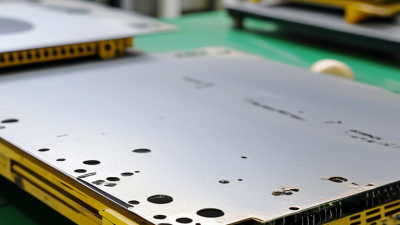
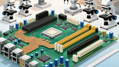
Choosing among today’s pcb types is not a simple catalog exercise. Each board reflects a different balance of cost, density, heat control, reliability, and production risk. A flexible circuit may fold through a compact medical device. A rigid multilayer board may manage high-speed signals inside industrial equipment. A metal-core PCB may move heat away from powerful LEDs more effectively than standard FR-4.
Happy Holden, a widely respected PCB manufacturing engineer and author, describes the board’s importance clearly: “The printed circuit board is the foundation of every electronic product.” His observation remains practical for global buyers. The wrong foundation can create assembly delays, signal problems, field failures, or unnecessary material costs.
This guide examines seven widely used pcb types and explains where each one performs best. It considers real purchasing concerns, including layer count, dielectric materials, impedance control, thermal paths, surface finishes, and supplier capabilities. It also connects technical choices with verification practices, such as IPC-based quality requirements, prototype testing, and documented inspection records.
Some decisions are obvious.
Others are not.
A low-cost board can become expensive when shipping, rework, or warranty claims appear later. A premium construction can also be excessive for a simple control circuit. That tension deserves careful review. Global sourcing adds further complexity because manufacturing equipment, certifications, communication standards, and inspection depth vary between suppliers.
The goal is not to name one universal winner. No such winner exists. Instead, this article helps engineers, purchasing teams, and product owners compare the seven best pcb types with clearer expectations, realistic constraints, and stronger technical judgment.
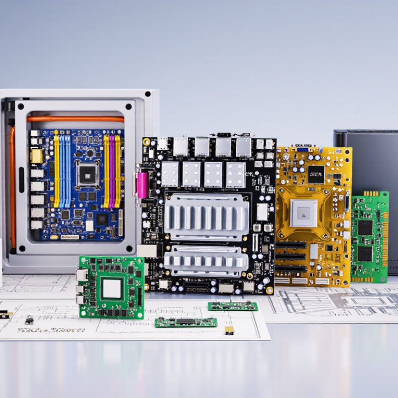
Global buyers often classify printed circuit boards by layer count, mechanical structure, and heat-management needs. The seven practical types are single-sided, double-sided, multilayer, rigid, flexible, rigid-flex, and metal-core PCBs. Single-sided boards suit simple controls and low-cost products. Double-sided boards support denser routing without excessive complexity. Multilayer boards handle compact systems, power distribution, and high-speed signals. Rigid boards provide stable support inside ordinary equipment.
Construction changes the purchasing logic. Flexible boards bend around hinges, cameras, and narrow spaces. Rigid-flex boards combine fixed support with controlled movement. Metal-core boards use a conductive base to move heat away from LEDs or power components. These categories can overlap. A multilayer board may also be flexible or metal-core.
Classification should match the product’s real operating conditions. Buyers should confirm layer count, copper thickness, dielectric material, bend radius, thermal requirements, and surface finish. For global sourcing, documentation matters as much as the board itself. Request drawings, controlled impedance data, inspection criteria, material declarations, and production samples. Regional standards may also affect safety, recycling, and chemical compliance.
In my sourcing experience, a low unit price can hide routing limits or costly assembly changes. Small details matter. A flexible circuit that bends once may fail after repeated movement. A rigid board may pass testing but crack under vibration. This classification is useful, not perfect. Product engineers and purchasing teams should review the same samples together. Their assumptions may differ. That is where avoidable mistakes often appear.
What Are the 7 Best PCB Types for Global Buyers?
Single-Sided and Double-Sided PCBs for Simple Electronic Designs
Single-sided PCBs suit simple circuits with limited components and straightforward current paths. Their copper layer sits on one side of the board. Components usually mount on the opposite surface. This structure reduces material use, assembly steps, and inspection complexity. It works well for basic control panels, LED boards, timers, and low-density sensors. However, routing becomes difficult when traces must cross each other. Wire links may solve the problem, but they can weaken production consistency.
Double-sided PCBs provide copper layers on both surfaces. Plated-through holes connect traces between layers. This allows denser layouts without greatly increasing board size. They support compact power supplies, measurement devices, and small automation modules. During sourcing, global buyers should request layer specifications, copper thickness, hole tolerance, and test records. These details reveal more than a low unit price. A reliable supplier should also provide material data and clear inspection procedures.
In practical prototype work, I have seen designers choose double-sided boards too early. The extra routing freedom was useful, but the design became harder to inspect. A single-sided board might have been enough. It is worth checking heat, spacing, connector access, and repair needs before ordering. Small mistakes matter. Regional documentation and shipping conditions can also affect approval and delivery. Clear files, consistent revisions, and traceable production records reduce avoidable surprises.
| PCB Type | Typical Layer Structure | Common Materials | Best-Fit Applications | Main Advantages | Key Limitations | Design Complexity | Relative Cost |
|---|---|---|---|---|---|---|---|
| Single-Sided PCB | One conductive copper layer on one side of the insulating substrate | FR-4, phenolic paper laminate, or CEM-1 |
|
|
|
Low | Very Low |
| Double-Sided PCB | Conductive copper layers on both sides of the substrate, usually connected by plated through-holes | FR-4 is widely used; high-temperature laminates may be selected for demanding environments |
|
|
|
Low to Medium | Low |
| Multilayer PCB | Three or more copper layers separated by dielectric material and bonded into one board | FR-4, high-Tg laminates, low-loss dielectric materials, or high-frequency laminates |
|
|
|
Medium to High | Medium to High |
| Flexible PCB | One or more copper layers on a bendable polymer film | Polyimide film, rolled-annealed copper, and flexible coverlay materials |
|
|
|
Medium to High | Medium to High |
| Rigid-Flex PCB | Rigid board sections permanently integrated with flexible PCB sections | FR-4 rigid laminates combined with polyimide flexible materials |
|
|
|
High | High |
| Metal-Core PCB | Copper circuitry built over a dielectric layer bonded to a metal base, commonly aluminum or copper | Aluminum core, copper core, thermally conductive dielectric, and copper foil |
|
|
|
Medium | Medium |
| HDI PCB | High-density multilayer construction using fine lines, microvias, and often sequential lamination | High-Tg FR-4, low-loss laminates, build-up dielectric materials, and copper foil |
|
|
|
High | High |
Cost and complexity are relative comparisons only. Actual results depend on board size, layer count, copper weight, material grade, tolerances, surface finish, testing requirements, order volume, and regional manufacturing conditions.
Global buyers can choose seven major PCB types: single-sided, double-sided, multilayer, HDI, flexible, rigid-flex, and metal-core boards. For dense, high-performance circuits, multilayer and HDI PCBs deserve closer attention. Fortune Business Insights valued the global PCB market at approximately US$89.7 billion in 2023. Its forecast reflects growing demand from automotive electronics, communications, and advanced computing.
Multilayer PCBs stack copper layers inside a compact board. This structure supports controlled impedance, separate power planes, and shorter signal paths. HDI PCBs add microvias, fine traces, and sequential buildup technology. They fit more connections around small processors and memory packages. Prismark’s 2024 market analysis identifies advanced interconnection technologies as important growth areas. Still, density is not automatically quality. Poor stackup planning can increase crosstalk, heat concentration, and repair difficulty. A practical review should examine via reliability, thermal cycling, material availability, and production yield. Small design choices matter.
Tips: Confirm the layer stack before layout begins. Use IPC-2221 principles for design planning and IPC-6012 requirements for qualification. Request cross-section samples from suppliers. Check impedance coupons, microvia reliability, and solder-mask registration. HDI can reduce board size, but it may raise fabrication costs and inspection demands. I have seen designs become unnecessarily complex because space savings were assumed, not measured. A simpler multilayer board may perform better when serviceability and stable production matter.
Multilayer and HDI PCBs support dense, high-performance circuits, while flex, rigid-flex, and metal-core boards address mechanical and thermal requirements. The chart shows representative copper-layer counts commonly used in each PCB type.
How to read the chart: A higher layer count generally provides more routing capacity and supports greater circuit density, but the best PCB type depends on electrical complexity, flexibility, thermal management, available space, and production requirements.
Flexible and Rigid-Flex PCBs for Compact, Moving Applications
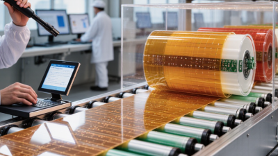
Flexible and rigid-flex PCBs support compact products with limited space and repeated movement. They replace bulky wire harnesses with thin copper circuits. This can reduce assembly steps, weight, and connection points. MarketsandMarkets estimates the flexible electronics market could reach about USD 87 billion by 2028. Its forecast indicates strong demand across automotive, medical, and consumer devices.
Flexible PCBs suit folding displays, wearable sensors, cameras, and moving control panels. Rigid-flex designs combine stable component areas with bendable interconnects. They can improve routing in crowded enclosures. However, bending rules matter. IPC-2223 and IPC-6013 provide useful design and qualification guidance. In practice, the bend radius, copper type, adhesive system, and coverlay thickness affect service life. A perfect drawing can still fail during assembly. Sharp tooling marks, uneven clamping, or repeated twisting may create hidden cracks.
Tips: Define the dynamic bend zone early. Keep vias away from that area. Use curved traces instead of sharp corners. Test the real motion cycle, not only a static sample. Also check temperature, humidity, and cleaning exposure. Research reports often show growth, but they cannot replace application-specific reliability testing. A smaller prototype may reveal routing stress before mass production. That step can feel slow. It is often cheaper than redesigning a finished enclosure.
Metal-Core PCBs for Heat Management and High-Power Electronics
Metal-core PCBs move heat away from LEDs, motor controllers, and power converters. Their metal base, usually aluminum or copper, sits beneath the dielectric layer. This structure shortens the thermal path to a heatsink. A practical design review should check thermal resistance, copper thickness, mounting pressure, and interface material together. One overlooked detail can undermine the whole assembly.
Demand is rising with electrification. The International Energy Agency reported nearly 14 million electric car sales in 2023, representing about 18% of global car sales. WSTS forecast the semiconductor market would reach 611.2 billion dollars in 2024. These figures indicate stronger demand for compact, heat-sensitive power electronics.
Metal-core boards can support that trend, especially in lighting, battery systems, chargers, and industrial drives.
Aluminum cores usually reduce weight and cost. Copper cores offer better thermal conductivity but add expense and mass. No universal winner exists. The dielectric layer still controls much of the thermal performance.
Designers should request tested thermal-impedance data, not rely only on marketing claims. IPC-2221 guidance can support spacing and current-capacity decisions, but it does not replace application testing.
I have seen layouts that looked thermally sound fail after enclosure changes. Airflow matters. So does rework. A careful prototype should measure hot spots under the real load, with the real interface material and mounting hardware.