
Why Choose Rigid Flex PCB for Your Next Project?
Why Choose Rigid Flex PCB for Your Next Project?
Modern products are shrinking while carrying more signals, power, and mechanical stress. A rigid flex pcb combines rigid board sections with flexible circuits, reducing connector count and saving valuable enclosure space. It can route signals around hinges, corners, batteries, and moving assemblies. Think of a compact medical monitor: one continuous circuit can replace several boards, wires, and hand-soldered connections.
Industry evidence supports this direction. IPC’s 2024 Electronics Industry Impact Report identifies miniaturization, reliability, and advanced interconnection technology as important electronics priorities. The 2024 Global Flexible Electronics Market report from Grand View Research also indicates continued expansion in flexible electronics, driven by wearables, healthcare devices, automotive systems, and consumer products. These reports do not prove that rigid-flex is always the best answer. Cost, layer design, bend radius, materials, and fabrication yield still matter.
Joe Fjelstad, a respected flexible-circuit engineer and author of Flexible Circuit Technology, has emphasized that flexible circuits should be designed as complete interconnection systems, not treated as simple wire replacements. That principle deserves attention. A rigid flex pcb may reduce assembly points, but poor bend planning can create copper fatigue, delamination, or early field failures. The real value appears when electrical, mechanical, and manufacturing teams work together from the first layout. It is not merely a thinner board. It is a different design decision. And sometimes, the honest conclusion is that a conventional rigid PCB remains the safer choice.
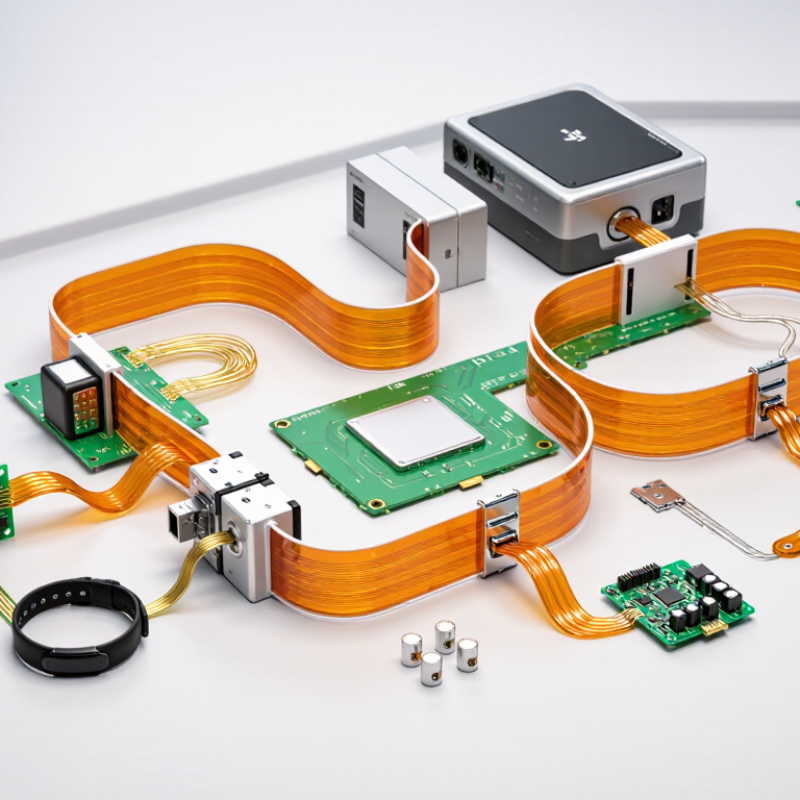
What Is a Rigid-Flex PCB?
A rigid-flex PCB combines rigid board sections with flexible circuit layers in one connected structure. The rigid zones support components, connectors, and mechanical mounting. The flexible zones bend through hinges, fold around frames, or pass through narrow spaces. Copper traces travel across both areas, while dielectric films and cover layers protect the conductors. This is more than a rigid board joined to a cable. Its materials, layer transitions, bend radius, and stress relief must work as one system.
During design reviews, engineers examine where the flex begins and how often it moves. A static fold needs different construction from a cable that bends thousands of times. The bend area should remain free of components and abrupt copper features. Rounded corners and gradual transitions can reduce concentrated stress. Small details matter. A careless stiffener edge can damage the flex over time. Impedance control, shielding, thermal paths, and connector retention also require early planning. Waiting until layout completion often creates expensive compromises.
Rigid-flex technology can reduce wire count, assembly steps, and package volume. It may also improve signal consistency by removing separate cable connections. However, it is not automatically cheaper or easier to manufacture. Material selection, stack-up accuracy, and controlled fabrication are essential for dependable results. Prototype testing should include folding, vibration, temperature cycling, and repeated insertion. I would not trust a beautiful first prototype without those tests. That judgment may seem cautious, but field failures are rarely convenient. With clear mechanical data and realistic bending requirements, a rigid-flex PCB becomes a practical three-dimensional interconnect.
Why Choose Rigid-Flex PCB for Your Next Project? - What Is a Rigid-Flex PCB?
| Design Dimension | Rigid PCB | Flexible PCB | Rigid-Flex PCB |
|---|---|---|---|
| Basic Construction | A solid multilayer or single-layer board made with rigid dielectric materials, commonly reinforced with glass fiber. | A bendable circuit made with flexible dielectric films, commonly polyimide, copper, and flexible coverlay. | A single interconnected structure combining rigid board sections with flexible circuit sections. |
| Bending Capability | Designed to remain flat; repeated bending can damage traces, solder joints, or the substrate. | Can be bent or folded when the bend radius, copper type, layer count, and material limits are respected. | Flexible zones can be folded or routed while rigid zones support components and connectors. |
| Typical Bend Guidance | Not intended for dynamic or static bending. | A common starting guideline is approximately 6–10 times the finished flex thickness for static bends; dynamic designs often require a larger radius and specialized validation. | The flexible section is commonly designed using approximately 10 times its finished thickness as an initial static-bend guideline, subject to material and supplier validation. |
| Mechanical Integration | Requires separate boards, cables, or connectors when multiple mechanical zones must be linked. | Integrates well into narrow or three-dimensional spaces but may need additional stiffeners for component mounting. | Supports three-dimensional packaging and can replace separate boards, cables, and some connectors. |
| Assembly Complexity | Generally straightforward for automated component placement and standard soldering processes. | May require fixtures, stiffeners, special handling, and careful control of bend areas during assembly. | Combines rigid-board assembly methods with flex handling requirements; tooling and bend-control procedures are important. |
| Interconnection Count | Often needs board-to-board connectors, wire harnesses, or discrete cables for separated assemblies. | Can reduce cable count, although separate connectors may still be required at board interfaces. | Can reduce connector, cable, and solder-joint count by integrating electrical and mechanical interconnections. |
| Space and Weight | Usually requires more enclosure volume when several boards and cables are used. | Very thin and lightweight, making it suitable for compact or moving assemblies. | Can reduce package volume and wiring mass while retaining rigid mounting areas for components. |
| Signal Integrity | Provides a stable platform for controlled-impedance traces and high-speed routing. | Can support controlled impedance, but bend geometry, material selection, and stack-up control require careful analysis. | Can maintain continuous routing across assemblies, but transitions between rigid and flex regions must be carefully designed. |
| Thermal Management | Rigid areas can use copper planes, thermal vias, and metal-backed constructions for heat spreading. | Limited by thin construction and reduced copper area; high-power zones often need additional thermal design. | Rigid sections can provide component support and heat-spreading capacity, while flex zones are best kept away from high-heat loads. |
| Reliability Considerations | Reliability depends on laminate quality, solder-joint design, thermal cycling, vibration, and mechanical support. | Reliability depends strongly on bend radius, flexing cycles, copper grain direction, strain relief, and protection of bend zones. | Can improve system reliability by reducing interconnects, but rigid-to-flex transitions require controlled geometry and mechanical support. |
| Manufacturing Cost Profile | Usually the most economical option for flat, high-volume designs with conventional layouts. | Typically costs more than a comparable rigid board because of flexible materials, coverlay, stiffeners, and handling requirements. | Often has a higher unit fabrication cost, but total system cost may decrease when cables, connectors, assembly steps, and space requirements are reduced. |
| Best-Fit Applications | Control units, power supplies, computing boards, fixed industrial electronics, and general-purpose assemblies. | Compact wearables, cameras, displays, sensors, printers, and applications requiring repeated or constrained movement. | Aerospace electronics, medical instruments, robotics, automotive modules, compact consumer devices, and assemblies with tight three-dimensional packaging. |
| When to Choose It | Choose it when the electronics can remain flat and separate cables or connectors are acceptable. | Choose it when repeated bending, folding, or routing through a narrow space is the primary requirement. | Choose it when a project needs both rigid component-support areas and flexible three-dimensional interconnection in one integrated assembly. |
Note: Bend-radius values are general design starting points rather than universal specifications. Final values should be confirmed through the selected materials, layer stack-up, copper type, bend frequency, temperature range, and qualification testing.
Related Posts
-

2026 Top PCB Fabrication Trends for Global Buyers?
-
How to Master Printed Circuit Board Manufacturing Techniques and Best Practices?
-

Essential Tips for Choosing the Right PCB Types for Your Needs?
-

2025 Strategies for PCB Prototyping to Improve Product Development Efficiency
-
Best PCB Production Techniques for Global Buyers?
-

Top 10 PCB Fabrication Services in China for Global Buyers?