Designing PCB flex circuits is an intricate process that requires careful consideration. These circuits are not just standard designs. They provide unique flexibility and compactness in various applications. When done right, PCB flex can enable enhanced functionality in devices.
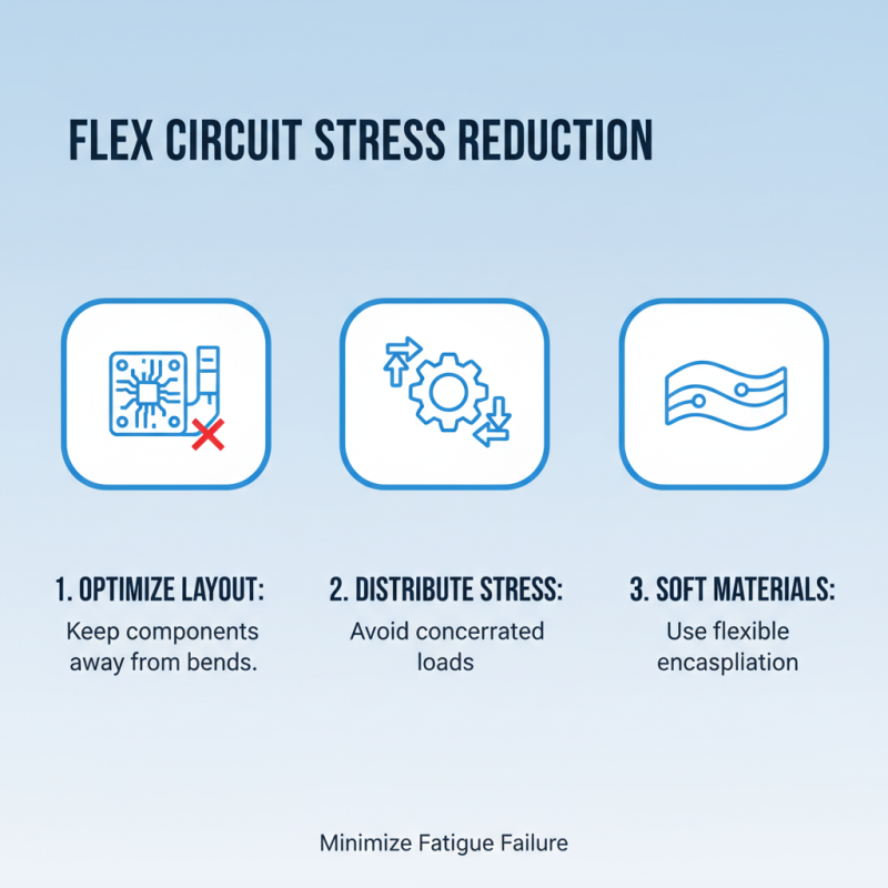
Understanding the challenges in designing PCB flex is essential. Engineers must account for the material properties and stress points. A miscalculation can lead to failures. Common issues include poor layer alignment and inadequate flex tolerance.
Effective design requires attention to detail. Each layer must be precisely aligned, and connections must be robust. Regular testing can help identify weaknesses early. With thoughtful design, PCB flex circuits can significantly improve electronic performance. Balancing creativity and precision is key for success.
Flex circuits have revolutionized the electronic design landscape. Understanding the basics of flex circuit design is crucial for engineers. These circuits allow for complex routing in tight spaces. They are lighter and thinner than traditional PCBs. According to industry reports, the global flex circuit market is projected to grow to $25.2 billion by 2027. This growth reflects the increasing demand for compact devices.
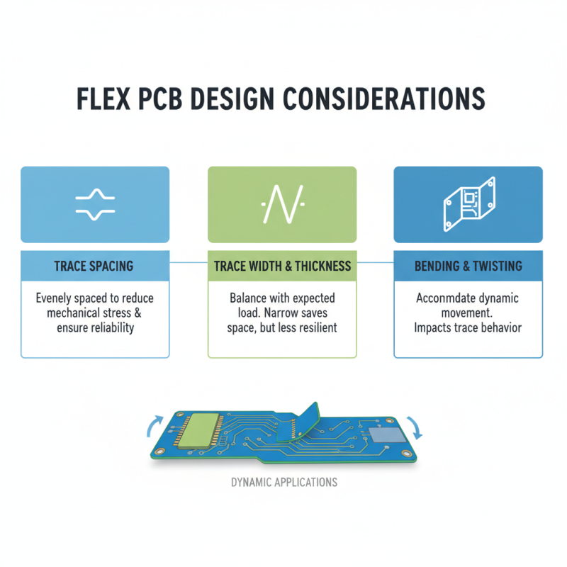
Designing flex circuits requires careful consideration. Material selection is vital. Polyimide is a common choice, but it can be expensive. Engineers must balance cost and performance. Additionally, the bend radius must be addressed. An inadequate radius can lead to mechanical failure. Flex circuits also need proper thermal management. Heat dissipation is often underestimated during the design phase.
Moreover, it is important to integrate testing early in the design. Flex circuits face unique challenges, including flexibility and durability. A reliable testing protocol can prevent costly redesigns later. Despite these hurdles, the design process remains iterative. Designers often find themselves revisiting previous steps. Reflecting on past designs can yield better results. Emphasis on collaboration and adaptation is key in the evolving landscape.
This bar chart represents essential design parameters for PCB flex circuits, including layer count, minimum trace width, minimum spacing, bend radius, and material thickness. Understanding these parameters is critical for successful flex circuit design.
When designing high-performance flex circuits, material selection plays a crucial role. The right materials ensure durability and efficiency in tight spaces. For instance, polyimide is often favored for its excellent thermal stability. A recent industry report notes that polyimide-based flex circuits can withstand temperatures exceeding 200°C.
However, not all applications require high thermal resistance. Designers must consider cost and flexibility. A study found that equipment in consumer electronics often uses PET (Polyethylene Terephthalate) because of its lower cost and adequate performance for less demanding environments. This choice can significantly reduce production costs while maintaining functionality.
Moreover, adhesion and lamination processes require careful attention. The bonding strength of chosen materials can affect circuit reliability. An analysis revealed that improper lamination can lead to premature failures. Therefore, it’s vital to test adhesive methods thoroughly to ensure durability. Choosing the correct materials is a balancing act that demands close attention to specific application requirements and performance metrics.
| Tip Number | Tip Description | Material Recommendation | Use Case |
|---|---|---|---|
| 1 | Choose the right substrate material. | Polyimide | High-temperature applications |
| 2 | Consider the thickness of the material. | 0.5mm - 1.0mm thickness | Compact devices |
| 3 | Optimize the layout for bending. | Lightweight flexible materials | Wearable technology |
| 4 | Select the right conductive traces. | Copper | Signal transmission |
| 5 | Ensure proper flexibility. | Flexible epoxy | Flexible circuits |
| 6 | Analyze environmental factors. | Thermal and moisture resistant materials | Outdoor equipment |
| 7 | Test for durability. | Durable polyimide | High-stress applications |
| 8 | Use appropriate adhesives. | Acrylic-based adhesives | Flexible bonding |
| 9 | Incorporate design for manufacturing (DFM). | CAD tools | Streamlined production |
| 10 | Ensure compliance with standards. | UL/IEC compliant materials | Safety and regulation adherence |
When designing flex PCBs, careful attention to traces and layout is crucial. Flex circuits can bend, twist, and fold, which influences how traces behave. Keep traces evenly spaced to reduce mechanical stress. This helps ensure reliability in dynamic applications. Narrow traces can save space but may not withstand stress well. Balance trace width and thickness with the expected load.
Using copper pours can distribute heat effectively across the board. However, remember that large pours can create complications during fabrication. Consider the layers of the PCB. More layers can lead to additional weight and complexity. Inflexible areas should be minimized to preserve the unique benefits of flex circuits.
Designing for bending requires strategic placement of components. Ensure that heavy components are positioned wisely. They should not be on the bending line. Think about how frequently the circuit will flex. Updating designs frequently can lead to problems. This iterative process demands reflection and a willingness to adapt. Testing your designs under real-life conditions is vital. This often reveals unexpected challenges that need addressing.
Designing flex circuits requires careful consideration to minimize mechanical stress. One effective technique is to optimize the layout. Keep high-stress components away from bends. This reduces the chance of fatigue failure. Use soft materials for covers or encapsulation. These materials can absorb some stress, protecting your circuit.
Another strategy is to design for flexibility. Incorporate curves instead of sharp angles. Smooth transitions distribute stress more evenly across the material. It’s essential to test prototypes under realistic conditions. You may find unexpected weak points. A small detail, like the thickness of the copper traces, can greatly impact performance.
Don’t overlook the importance of the assembly process. Ensure that components are not overly torqued. Excessive force during assembly may introduce stress. Evaluate the way the circuit will be handled in its final application. There can be unseen stresses during use. Each design phase is a chance to reflect on these factors. A thoughtful approach can lead to more reliable and durable flex circuits.
Testing and quality assurance for flex circuits are critical steps in the design process. Flex circuits are often subjected to various mechanical stresses. These can lead to failures if not properly tested. A recent report noted that up to 30% of flex circuit failures stem from inadequate testing protocols. This highlights the need for rigorous quality checks.
One effective testing method is the use of bending and flexural tests. These tests simulate real-world applications. They help in assessing the durability of the circuit. Some manufacturers conduct thermal cycling tests. They expose the flex circuits to extreme temperature variations. This ensures the components can withstand harsh conditions. However, many companies overlook these tests, risking product reliability.
Designers should also focus on visual inspections. A simple visual check can reveal surface defects. Manufacturers should train their staff to spot these flaws. Ignoring small imperfections can lead to larger issues down the line. Additionally, engineers need to track and document testing results systematically. Poor data management can mask trends in failures, preventing necessary adjustments.